Many outdoor and smart devices require a stable 12V power supply, even when the available battery source is a single 3.2V LiFePO4 cell or a 3.7V lithium-ion or lithium polymer cell. In these projects, the battery is only one part of the complete power system.
A practical design may need battery charging, solar input, DC boost conversion, output regulation and battery protection to work together as one solution. This article explains how a low-voltage lithium battery can support regulated 12V devices when combined with the right power management design.
3.2V and 3.7V Lithium Battery to 12V Output
A single 3.2V LiFePO4 cell or 3.7V lithium cell cannot directly supply a stable 12V load. A DC boost conversion stage is required to raise the battery voltage to a regulated 12V output.
The typical power path can be described as:
Lithium battery input → battery protection and charging control → DC boost conversion → regulated 12V output
This type of architecture is used in monitoring equipment, solar-powered devices, IoT terminals, small controllers, communication modules and other compact electronic systems that need 12V output but cannot use a large 12V battery pack.
Example Power Management Board
The example below shows a power management board designed for low-voltage lithium battery input, solar charging and regulated 12V output. It is shown as a reference for system understanding, not as a universal specification for every project.
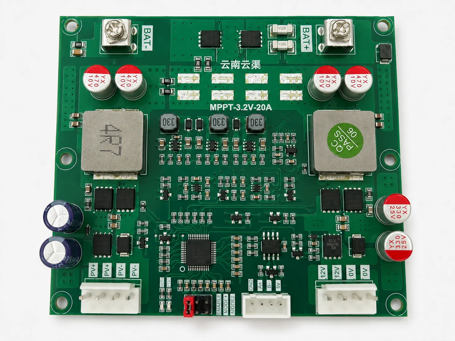
The front side includes connection areas for battery input, solar PV input, control signals and regulated output. Components such as inductors, capacitors, MOSFETs, control ICs and connectors are part of the power conversion and management circuit.
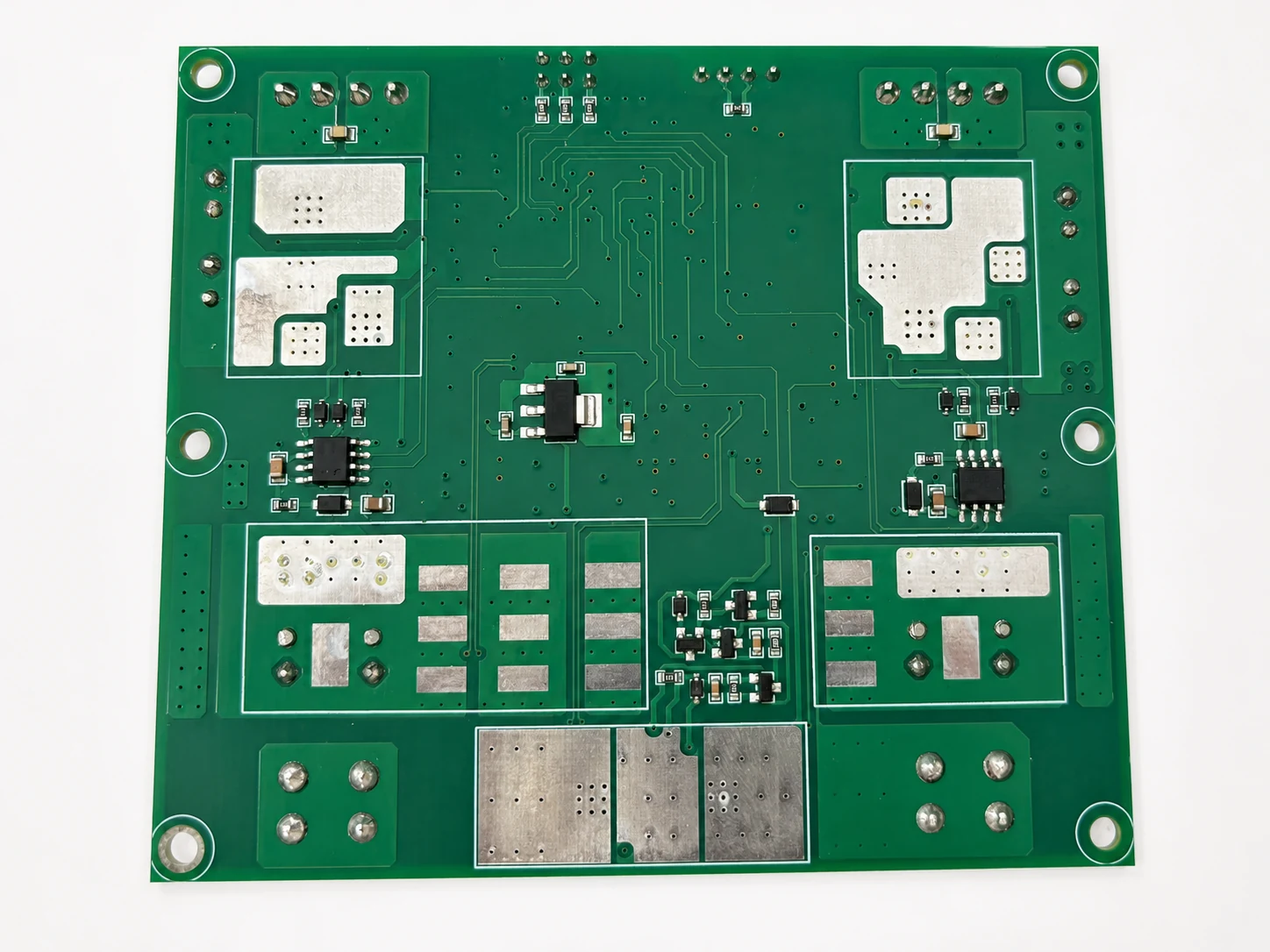
The back side shows PCB traces, solder pads and connection areas. For OEM projects, the final circuit layout, charging current, output current, connector type and protection settings should be evaluated according to the device design.
Solar PV Charging Input
For solar-powered equipment, a solar PV input can be used to charge the battery through a charging management circuit. In the reference configuration, the PV input range may be approximately 10–30V, depending on the system design and solar panel selection.
The charging power is typically limited by the board design, thermal conditions, solar panel output and battery configuration. For this type of compact board, charging power may be below approximately 70W in the reference design.
Solar charging performance should always be checked together with the actual solar panel, battery chemistry, enclosure temperature and device power consumption.
Battery Charging Voltage for LiFePO4 and Lithium-Ion Cells
Different lithium battery chemistries require different charging voltage settings. A 3.2V LiFePO4 cell is different from a 3.7V lithium-ion or lithium polymer cell.
For a single LiFePO4 cell, the upper charging voltage is often around 3.6V per cell, depending on the selected cell and charging strategy. This value should be treated as a reference and confirmed against the actual battery cell specification.
For 3.7V lithium-ion or lithium polymer batteries, charging parameters are different and must be confirmed according to the actual cell model, protection circuit and application requirements. The same charging settings should not be applied across different chemistries without engineering review.
ASOL can support LiFePO4 battery solution, cylindrical lithium-ion battery pack and lithium polymer battery evaluation based on project requirements.
Discharge and Low-Voltage Protection
Battery protection is important when a low-voltage lithium battery is used to support a 12V load. Without proper protection, the battery may be over-discharged when the device continues operating after the battery voltage becomes too low.
For a single LiFePO4 cell, the low-voltage cut-off reference may be around 2.65–2.7V, depending on the cell specification and protection design. This value is not a universal setting for all lithium batteries.
For 3.7V lithium-ion or lithium polymer batteries, over-discharge protection values must be selected according to the actual cell and protection circuit. OEM projects should confirm these details before mass production.
12V Output for Monitoring and Smart Devices
The regulated output of this type of power system is commonly designed around 12V. In the reference configuration, the output current may reach up to around 5A, with output power up to around 60W, depending on thermal conditions, board design and operating environment.
This makes the architecture suitable for many low-power and medium-power 12V devices, such as remote sensors, wireless communication devices, security equipment, monitoring terminals, solar-powered controllers and compact electronic modules.
However, the final output capability should be evaluated according to peak load current, continuous load current, ambient temperature, enclosure ventilation and battery discharge capability.
An Alternative to a Traditional 12V Battery Pack
Some devices require 12V output but do not have enough space for a traditional multi-cell 12V lithium battery pack. In these cases, a single-cell lithium battery combined with boost conversion may offer a more compact design path.
This approach may help equipment designers reduce battery size, simplify cell configuration and support solar charging in compact products. It is especially useful when the device power requirement is moderate and the operating current can be managed within the boost converter design limits.
It should not be treated as a direct replacement for every 12V battery pack. Higher-power equipment, long-runtime systems or harsh operating environments may still require a dedicated multi-cell lithium battery pack.
Why Battery and Power Electronics Should Be Evaluated Together
For B2B device projects, the battery and the power management circuit should be selected together. A suitable battery must match the charging circuit, discharge current, protection settings, connector design, enclosure space and operating environment.
Key factors include battery chemistry, capacity, discharge current, charging voltage, solar input conditions, output load, PCB temperature rise, connector reliability and safety protection.
When these factors are evaluated separately, the final device may face problems such as unstable 12V output, insufficient runtime, excessive heat, poor solar charging performance or reduced battery life.
Custom 3.2V / 3.7V to 12V Lithium Battery Solutions
ASOL Battery focuses on lithium battery solutions for OEM and industrial equipment projects. For devices that require 3.2V LiFePO4 or 3.7V lithium battery input with regulated 12V output, ASOL can help evaluate battery chemistry, capacity, protection requirements, connector options and power system compatibility.
ASOL is not positioning this type of project as a standalone PCB or solar controller product. The focus is to support equipment manufacturers with battery selection and power solution evaluation for real application conditions.
If your project requires a compact battery system with solar charging and regulated 12V output, ASOL can review the battery requirements together with the device power profile and help develop a practical custom lithium battery solution.
Have a 12V device project with specific battery size, runtime or solar charging requirements? Contact ASOL to discuss your battery configuration.