Battery Knowledge
Table of Contents
- 1. How Much Current Does a 3.5kW Inverter Draw?
- 2. Why 200Ah Alone Does Not Determine Compatibility
- 3. ASOL 25.6V 200Ah + 3.5kW Inverter Example
- 4. Five Checks Before Connecting the Inverter
- 5. What About Runtime?
- 6. When Would a Different Battery Configuration Be Needed?
- 7. What Information Should You Provide for a System Review?
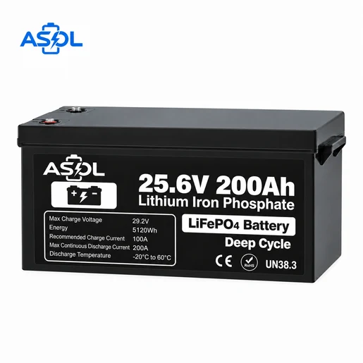
A properly configured 25.6V 200Ah LiFePO4 battery can support a 3.5kW inverter when the battery's continuous discharge capability, BMS rating, inverter surge demand, DC input range, cabling and charging system are compatible.
Battery capacity alone does not determine inverter compatibility. The system review must consider both stored energy and the current the battery and BMS must deliver under steady load and startup conditions.
How Much Current Does a 3.5kW Inverter Draw?
The starting calculation is Current = Power ÷ Voltage. At the battery's nominal voltage:
3500W ÷ 25.6V = 136.7A, or approximately 137A.
This is an ideal, theoretical battery-side current before inverter losses. For illustration only, if an inverter operated at 90% efficiency:
3500W ÷ (25.6V × 0.90) = 151.9A, or approximately 152A.
The 90% value is not a claim about every inverter or a customer's inverter. Actual battery-side current depends on inverter efficiency, instantaneous battery voltage, actual AC load and system losses.
A 3.5kW inverter rating also does not mean the inverter continuously draws 3.5kW. Battery current follows the connected load, while standby consumption and inverter self-consumption add to the system demand. For design review, use the highest expected sustained AC load rather than assuming either zero load or full rated power at all times.
As battery voltage decreases, more current is required to deliver the same power. The following table uses the same illustrative 90% efficiency assumption:
| Battery-side voltage | Example current at 90% efficiency |
|---|---|
| 25.6V | ≈152A |
| 24.0V | ≈162A |
| 22.0V | ≈177A |
The current standard battery lists 21.6V as its discharge cut-off voltage. That value is a protection boundary, not a recommended normal operating voltage. An inverter may enter low-voltage shutdown at a higher battery voltage depending on its DC input specification.
Why 200Ah Alone Does Not Determine Compatibility
Energy capacity and power/current capability answer different questions. At nominal values, 25.6V × 200Ah = 5.12kWh. This tells the buyer how much nominal energy is stored.
It does not establish whether the battery and BMS can supply the current required by a 3.5kW inverter. A 200Ah battery may store enough energy for an application but still be unsuitable if its BMS cannot supply the required continuous or surge current.
ASOL 25.6V 200Ah + 3.5kW Inverter Example
The current standard 25.6V 200Ah LiFePO4 Battery has the following verified values:
| Item | Value |
|---|---|
| Battery nominal voltage | 25.6V |
| Battery capacity | 200Ah |
| Nominal energy | 5.12kWh |
| 3.5kW ideal current at 25.6V | ≈137A |
| Illustrative current at 90% inverter efficiency | ≈152A |
| ASOL standard maximum continuous discharge | 200A |
| ASOL peak discharge | 250A |
At nominal battery voltage, the calculated steady-state current is below the standard 200A maximum continuous-discharge rating. This comparison is not a universal compatibility guarantee. Final suitability still depends on actual inverter efficiency, inverter DC input-voltage range, low-voltage behavior, surge power and duration, installation conditions and the charging system.
The lower-voltage examples show why the nominal-voltage comparison is only the first check. At the same 3.5kW AC load, the illustrative current rises to approximately 177A at 22.0V. Cable voltage drop, connector resistance and protection settings can further affect the voltage seen at the inverter, so the complete current path must be evaluated under load.
Peak-current compatibility cannot be determined from the current value alone. The inverter surge magnitude and duration must be compared with the approved BMS peak-current duration for the final battery configuration. The current product page does not publish a peak duration, so no duration should be assumed from the 250A value.
Five Checks Before Connecting the Inverter
1. Inverter Surge Power and Duration
Rated power describes sustained output; surge or startup power describes a temporary demand. Air conditioners, compressors, pumps, motors and refrigeration equipment can impose startup loads that differ from their normal running loads. Obtain both surge magnitude and surge duration from the inverter and load specifications, then compare them with the approved battery/BMS limits.
2. Inverter DC Input Voltage Range
A “24V inverter” label alone does not prove compatibility. Check nominal DC input voltage, minimum DC input voltage, low-voltage cut-off and maximum DC input voltage. Compare these with the battery's 29.2V maximum charge voltage and 21.6V listed discharge cut-off voltage. The inverter should not be assumed to operate normally down to the battery cut-off.
3. BMS Continuous and Peak Current
The BMS must support the expected continuous load and the short-duration surge. For this specific standard ASOL configuration, the verified figures are 200A maximum continuous discharge and 250A peak discharge. These figures do not apply automatically to every ASOL 25.6V battery or to a modified project configuration.
4. Cable, Fuse and Terminal Requirements
High-current DC systems require conductor cross-section, cable length, allowable voltage drop, fuse or breaker, terminal capability and installation conditions to be reviewed together. A single AWG, mm² or fuse rating cannot be prescribed without the actual current, cable route, ambient conditions and protection design.
The protection device should coordinate with the cable, battery/BMS limit and inverter requirement. Terminal preparation and connection torque must follow the applicable component instructions; a high-current rating on paper does not compensate for an unsuitable cable run or poor connection.
5. Charging System
Charging may come from an all-in-one solar inverter, MPPT charger, mains charger, generator/charger or other compatible DC charging equipment. Confirm charge voltage, charge current and the LiFePO4 charging profile. For this standard battery, the recommended charge current is 100A, maximum charge current is 200A and maximum charge voltage is 29.2V.
What About Runtime?
The nominal calculation is 5.12kWh ÷ 3.5kW ≈ 1.46 hours. This is only a nominal mathematical result and must not be interpreted as expected or guaranteed runtime.
Actual runtime depends on inverter efficiency, actual usable battery energy, inverter and BMS cut-off settings, the real load profile, temperature and DC losses.
When Would a Different Battery Configuration Be Needed?
A different configuration may be required when the surge demand exceeds approved battery/BMS capability, the continuous current approaches or exceeds approved limits, longer runtime or higher inverter power is needed, redundancy is required, installation dimensions require another arrangement, or the charging system requires a different battery configuration.
Series or parallel operation must be reviewed for the specific model and approved configuration. No universal ASOL series or parallel limit should be inferred.
What Information Should You Provide for a System Review?
For a technical review, provide the inverter rated power, inverter surge power, surge duration, DC input voltage range, main electrical loads, expected continuous load, charging source, charger voltage/current, required operating time, available installation space, ambient operating conditions and required quantity.
For broader specification planning, the Lithium Battery Pack Buying Guide explains how electrical, mechanical and charging requirements fit into a complete B2B RFQ.
Conclusion
Yes—the standard ASOL 25.6V 200Ah configuration can be evaluated for a 3.5kW inverter system. At 25.6V and an illustrative 90% inverter efficiency, a 3.5kW AC load requires approximately 152A from the battery side, which is below the verified standard battery's 200A maximum continuous-discharge rating.
Final compatibility still depends on inverter surge power and duration, DC input-voltage range, low-voltage cut-off, actual load profile, cabling and protection, and the charging configuration.
Request a System-Matching Review
Share the inverter specification, load profile, charging source, installation space, operating conditions and planned quantity with ASOL for configuration review.